
Page 9 - Piper PA-18 Super Cub Parts Catalog
P. 9
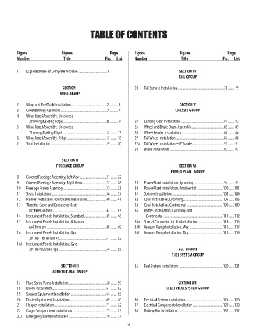
TABLE OF CONTENTS


         Figure               Figure                 Page        Figure               Figure                 Page
         Number                Title               Fig.  List    Number                Title               Fig.  List


         1    Exploded View of Complete Airplane ................................1    SECTION IV
                                                                                      TAIL GROUP

                               SECTION I                         23   Tail Surface Installation ...................................................78 ....... 79
                             WING GROUP

         2    Wing and Fuel Tank Installation ........................................2 ......... 3  SECTION V
         3    Covered Wing Assembly ....................................................7 ......... 7  CHASSIS GROUP
         4    Wing Panel Assembly, Uncovered
                         (Showing Leading Edge) ................................................8 ......... 9  24   Landing Gear Installation ................................................81 ....... 82
         5    Wing Panel Assembly, Uncovered                     25   Wheel and Brake Drum Assembly ....................................85 ....... 85
                         (Showing Trailing Edge) ................................................12 ....... 13  26   Wheel Fender Installation ...............................................86 ....... 86
         6    Wing Panel Assembly, 95hp ............................................17 ....... 18  27   Tail Wheel Installation .....................................................87 ....... 88
         7    Strut Installation .............................................................19 ....... 20  27A  Tail Wheel Installation – 8” Maule ...................................91 ....... 91
                                                                 28   Brake Installation ............................................................92 ....... 93


                              SECTION II
                            FUSELAGE GROUP                                            SECTION VI
                                                                                  POWER PLANT GROUP
         8    Covered Fuselage Assembly, Left View .............................21 ....... 22
         9    Covered Fuselage Assembly, Right View ..........................27 ....... 28  29   Power Plant Installation, Lycoming .................................94 ....... 95
         10   Fuselage Frame Assembly ...............................................32 ....... 33  30   Power Plant Installation, Continental .............................100 ..... 101
         11   Seats Installation .............................................................36 ....... 37  31   Spinner Installation ........................................................103 ..... 104
         12   Rudder Pedals and Floorboards Installation .....................40 ....... 41  32   Cowl Installation, Lycoming ............................................105 ..... 106
         13   Throttle, Cabin and Carburetor Heat                33   Cowl Installation, Continental ........................................108 ..... 109
                         Mixture Controls ............................................................42 ....... 43  34   Baffles Installation, Lycoming and
         14   Instrument Panels Installation, Standard ........................45 ....... 46                  Continental ..................................................................111 ..... 112
         15   Instrument Panels Installation, Advanced           34A  Special Carburetor Air Box Installation ............................114 ..... 115
                         and Primary ..................................................................48 ....... 49  34B  Vacuum Pump Installation, Wet .....................................116 ..... 117
         16   Instrument Panels Installation, Gyro               34C  Vacuum Pump Installation, Dry ......................................118 ..... 119
                         (SN 18-1 to 18-8019) ....................................................51 ....... 52
         16A  Instrument Panels Installation, Gyro
                         (SN 18-8020 and up) .....................................................54 ....... 55  SECTION VII
                                                                                  FUEL SYSTEM GROUP

                              SECTION III                        35   Fuel System Installation .................................................120 ..... 121
                          AGRICULTURAL GROUP

         17   Fluid Spray Pump Installation ..........................................58 ....... 59  SECTION Vlll
         18   Boom Installation ............................................................61 ....... 62  ELECTRICAL SYSTEM GROUP
         19   Sprayer Equipment Installation .......................................64 ....... 65
         20   Duster Equipment Installation .........................................69 ....... 70  36   Electrical System Installation ..........................................125 ..... 126
         21   Hopper Installation ..........................................................71 ....... 72  37   Electrical Components Installation .................................129 ..... 130
         22   Cargo Compartment Installation .....................................75 ....... 75  38   Battery Box Installation ..................................................132 ..... 132
         22A  Emergency Dump Installation .........................................76 ....... 77
                                                             vii